SDP 2020: WeatherBox
Weather Box is a low-cost, low-power weather sensing solution that sends weather data to a web server on Microsoft Azure. Created for UMass ECE Senior Design Project 2020.
Team
- Advisor: Professor Michael Zink
- Software Lead: Anthony Mendez
- Hardware Lead: Tina Maurer
- Communications: Stephan Kim
- Website and Interpolation: Christian Nortan
Special Thanks
Special thanks to many people throughout this project. First and foremost, thank you to Professor Zink for all the support and assistance he provided throughout the project. I would also like to thank Professor Tessier and Professor Pishro-Nik for their feedback during peer review, as well as Professor Holcomb for stepping in as a reviewer for CDR. Another round of thanks to the M5 staff, for allowing us to use their tools and components. And finally, thank you to the Provost office for aiding us in collecting additional funds for the poroject, and Apoorva Bajaj for assisiting us in the initial research.
Abstract
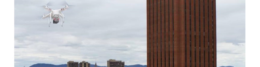
As part of pre-flight preparations, drone operators must check the local weather conditions to ensure a safe and successful flight. While commercial weather stations can effectively collect data for a specified area at the macroscale, weather conditions in that area at the microscale can vary greatly. Since flight conditions can be greatly affected by these constraints, drone operators need a more accurate localized weather map reading for the area of flight. Weather Box will create this localized map in a network of battery-powered sensor modules to provide drone users with the required information via a website and application. Our product will allow operators to quickly decide whether the conditions are suitable for safe drone flight.
Development
The development of the project was broken up into four main sections quarters. Preliminary Design Review, Midway Design Review, Cumulative Design Review, and Final Design Review.
The majority of this section is written from my perspective and meant to be reflective of my own work. So any deep technical insight, especially on the hardware side should not be expected.
Preliminary Design Review
When we were coming up with a project idea, we didn’t know what route or domain we wanted to go in.
Professor Christopher Hollot let us know in an email with a few projects that some researchers and companies in our department had. So we talked to one of the researchers about their project. The researcher we talked to was Apoorva Bajaj. His project was something along the lines of figuring out weather conditions, more specifically wind speed and direction, before deploying a drone for emergency operations. This information is critical in knowing whether not conditions were safe for a drone to fly in.
Of course, for Senior Design Project, this project presented a few challenges. How can we accurately measure wind speed and direction? How can we test this out with a drone when none of us have any drone flying experience or an FAA license?
In the end, we decided to scale back the project, and make our project more general purpose. We came up with the following design:
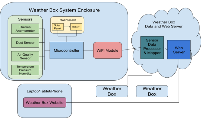
First off, the sensors. We intended to use the following sensors:
- Bosch BME280 Temperature Pressure and Humidity Sensor
- SHARP GP2Y1010AU0F Dust Sensor
- ams AG CCS811B-JOPD Air Quality Sensor
- Modern Device Wind Sensor Rev. P Thermal Anemometer
Each of the sensors are capable of measuring at a sampling rate of 1 measurement every 10 seconds. The sensors were cheap as well, costing an estimated $50 for a set.
Next is the power source. We were planning on using a solar cell along with a battery to charge and power our system. We estimated it would’ve cost about $30. We had no specific battery or solar cell in mind.
For our microcontroller, we decided to go with an STM32 microcontroller. More specifically, the STM32L073RZ microcontroller. STM32 also provides development boards called Nucleo boards. So we used the NUCLEO-L073RZ for initial development and testing. We chose STM32 because Tina has experience using these microcontrollers from her work experience. We narrowed down to the L073RZ for its expanded flash memory, and it’s low power draw. The development boards are cheap, going for around $12, while the microcontrollers themselves go around $5.
In order to transmit our data, we needed a Wi-Fi module. We decided on the Espressif Systems ESP8266 module. The ESP8266 is a popular choice in the Arduino community, and it’s relatively easy to program for. One module costs about $7.
On the web server side, we decided to go with Microsoft’s Azure to host our website. They offer discounted and free resources for students, and quick and easy setup for web applications. We decided to go for the Python library Flask for the web server since it is easy to prototype with and it is an extensive library with documentation.
For Midway Design Review, we promised these deliverables:
- Two sensor packages capable of measuring simulated wind speed, temperature, and barometric pressure (including protoboard for custom sensor PCB)
- Basic weather map created by the two sensor packages in a small and simulated test environment
- UI able to display raw data from Weather Boxes to a remote server terminal
We provided these as the initial System Specifications:
- Each unit will take measurements at its location and the web server must create a map of at least 150x50 m2 based on data from sensor packages
- Each sensor package must be mountable and weigh less than one pound
- System must measure wind, temperature, barometric pressure, humidity, dust, and air quality
- A battery life of at least 24 hours
- System must be operable in the range of 20 degrees Fahrenheit to 100 degrees Fahrenheit
- Be able to transmit weather measurements wirelessly to a user interface
- Each unit must be manufacturable for at most $120
We also provided an overall project stretch goal that we want to mount a Weather Box to a drone for real-time weather conditions at different altitudes. If we were to go this route, we would focus more on the public safety aspect, such as helping police decide if conditions are suitable for a drone mission.
Midway Design Review
After Preliminary Design Review, we modified our solution going forward based off some recommendations of our reviewers.
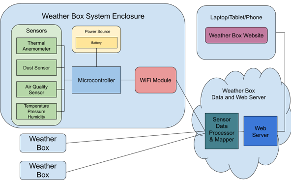
We decided to remove the solar cell from the power system to simplify designing the power circuitry. As well as change some of our System Specifications
- Each sensor package will take measurements at its location and the web server must create a map of at least 75x50 m2 based on data from sensor packages
- Each sensor package must be mountable and weighs less than one pound
- Each sensor package must measure wind, temperature, barometric pressure, humidity, dust, and air quality with 95% confidence
- Each sensor package must have a battery life of at least 24 hours
- Sensor package must be operable in the range of 20 degrees Fahrenheit to 100 degrees Fahrenheit
- Each sensor package should be able to transmit sensor data to a web server via WiFi
- Each sensor package must be manufacturable for at most $120
We downsized the size of the map to 75 x 50 meters squared. We added in a confidence interval for to hit achieve some amount of accuracy. Removed any mention of the solar cell. And finally, specified it will transmit data over Wi-Fi. Because of this, we also changed our deliverables to better match the system specifications.
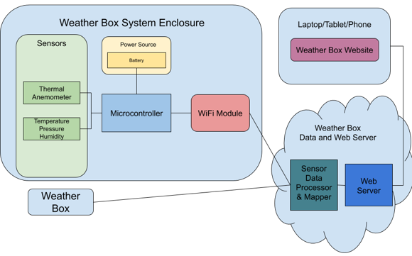
- Two fixed point development sensor boards that measure temperature, air pressure, humidity, and wind speed
- Temperature between 30°F - 80°F with 95% confidence
- Air pressure between 1.00atm - 0.96atm with 95% confidence
- Humidity between 0% - 100% with 95% confidence
- Wind speed between 0mph - 50mph with 95% confidence
- The sensor package will be powered by a battery
- Map displaying the location and data points of each sensor package
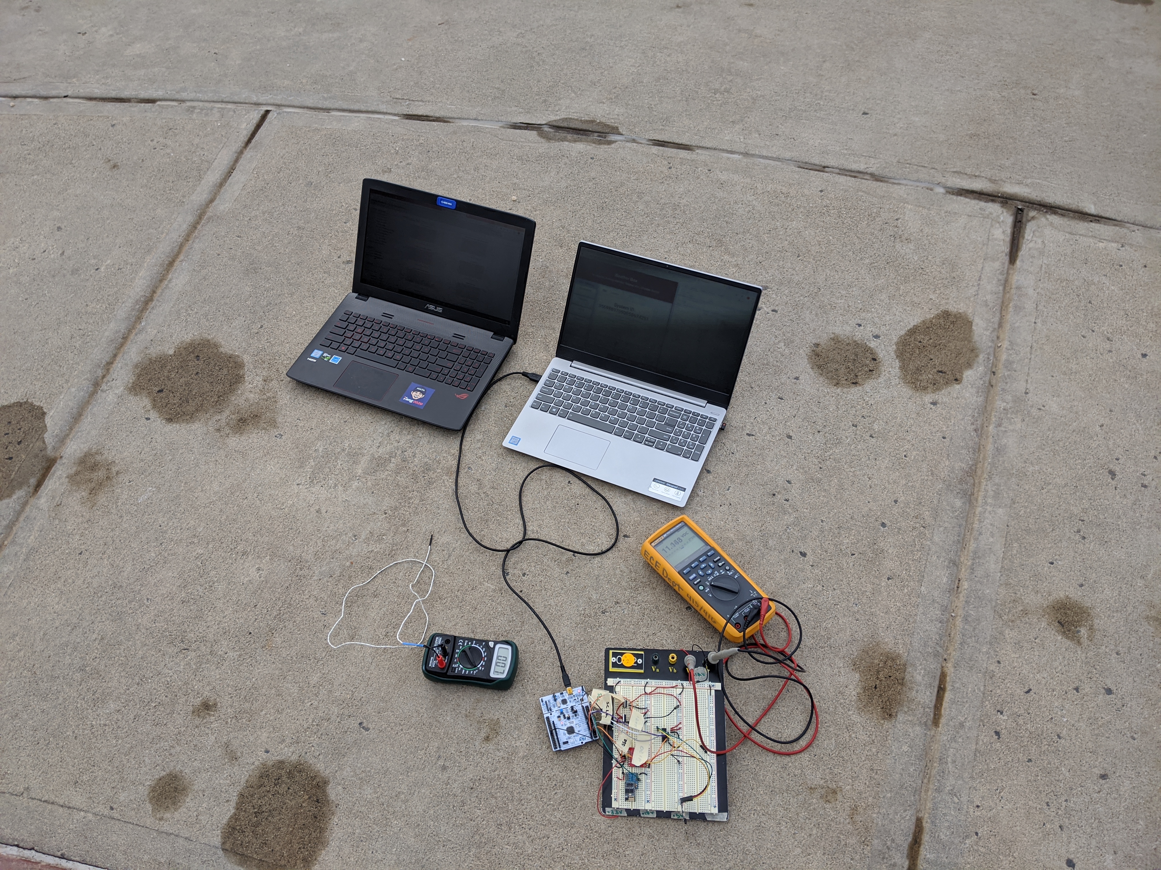
With this, we began work on the prototype. Tina set to work designing the power circuitry. I went ahead setting up how our project’s overall software loop would work out. In the early stages this hard to design. Even more so since we don’t have that much experience designing systems like these from the ground up. However, with a lot of Googling, and perseverance we were able to get a good prototype down for MDR.
Power Circuitry
Since I was not in charge of the power circuit, I asked Tina if she could do a write-up.
“We determined the requirements for the power circuitry based on the supply voltages required for the various sensors, MCU, and wifi module in the system. The necessary supplies were at +3.3V, +5V, and +12V. We used a +12V battery stack of AA batteries, giving us the capacity necessary to run the system for over 24 hours.
“In the first stage of this project, we implemented two step-down LDO regulators, one from the stack to obtain +5V, and the other connected to the +5V to obtain the +3.3V line. While this gave us stable supply lines for all components, each system drew over 100mA at all times, making this a high-power and fairly inefficient solution.”
For MDR, this “fairly inefficient solution” worked pretty well. However, for CDR, Tina ended up changing our power solution. More on that later.
Firmware
Starting with the Nucleo boards, we weren’t sure how to exactly start developing for it. STM32 provides some good documentation and starter projects for getting something set up and working. We decided to start doing some minimal changes just to test see how STM32 IDE works. One of the first things we set up was the interrupt timer. We set up the interrupt timer so that the microcontroller would read the sensors every 10 seconds. This was easy to do as the STM32 provides an interface called the Cube to modify the behavior and properties of components, like the internal ADC, GPIO pins, etc. So Stephan was able to modify some of the timer’s parameters to go off about every 10 seconds. We were able to test this by toggling an LED on the Nucleo board.
The next step was getting the Bosch BME280 sensor connected and working. After reading through some documentation on the sensor, the sensor utilizes the I2C communication protocol, as did our microcontroller. The Bosch sensor required a connection to ground, I2C SDA (Serial Data), I2C SCL (Serial Clock), and 3.3V power. With Tina’s power circuitry, hooking up ground and 3.3V was no problem. To get I2C working on the microcontroller, we had to enable I2C in the Cube interface, select two GPIO pins as SCL and SDA wires, then hooked them up.
Once the sensor was hooked up, programming the sensor was straight-forward… somewhat. STM projects come with the HAL API. The API abstracts a lot of the work needed to use certain features on the microcontroller. Bosch also provides a C driver that we implemented in our project. The way the driver works, we pass in function pointers for a read, write and delay, and the driver will handle initializing the sensor and settings. So everytime the microcontroller is powered up, it will initialize the sensor. Afterward, everytime the interrupt function runs, it will use the driver’s read data function.
The Wi-Fi module was tricky. It uses USART to communicate data with the microcontroller. But in order to control the module, we had to send in AT commands. This made debugging a little bit more difficult since we couldn’t see what exactly was going on. So we hooked up an Arduino board to listen in on the USART communications. We used the Arduino Serial Monitor to see all the response codes between the return from the module. Once we got the module connected to the Wi-Fi, we set up an HTTP Post command to our website with the data formatted in a JSON string.
Web Server
When we were deciding what language to use for our web-server, we decided on Python for a variety of reasons. The first is the Python is a very easy language to prototype with. It doesn’t take much work just to get something up and running. The second is that there are a lot of resources online Python’s web server library, Flask. The documentation for Flask is already really good. It’s further topped with all the Stack Overflow questions and answers available online. The third is that we wanted to use more Python since our academic and work experience has us using C or Java more often then not. We wanted to widen our programming experience and try using something completely different than what we’re used to.
After we established Python as our programming language, we decided to go with vanilla SQL for our database. The reason is that this was the only option available for the Azure Student Pack, and it would only cost us $5 a month for a few gigabytes. This was plenty.
The first thing we needed to do was for the web server to be able to receive the HTTP Post data from our microcontrollers. This was easy enough as Flask makes it really easy to define URL routes with the request type. Afterward, we verify the data type is a JSON, extract the data from the JSON, and then store it to the SQL database.
Ahh but storing the SQL database is another headache. In order to post the SQL database, we had to do a few things. The first was to add the pyodbc module to run SQL queries. Using this library, we need to format a connection string. The connection string consists of the type of SQL driver being used, the name of the SQL server, the database name, the PORT (usually 1433), the username, and the password. Once this connection string is set, we set whatever queries need to save the data to the database, execute, then commit the changes.
Retrieving data is nearly the same process. Set up an HTTP Get route. Create a query to retrieve data from the SQL server. Format that data into a JSON string, then send to the client.
Website
TBD:
 \
\
Cumulative Design Review
Power Circuitry
Continuing where Tina left off…
“So, in the later stages of the project, we swapped the LDO regulators for low-power switching regulators. As we only transmitted data to the server every 10 seconds, it was not necessary to have a regulator which operated constantly. This allowed us to lower our power consumption significantly and create a more efficient system. The switching regulators are each connected to the battery stack to create the other rails.”
Firmware
TBD:
Web Server
TBD:
Final Project Review
Because of coronavirus, we could never fully complete the project. TThe in-lab portion of the project was canceled.